 |
| home | eyetracking | computing | aesthetics | research |
| software -- microcontrollers/breadboards -- generative algorithms |
|
Driving a Unipolar Stepper Motor: This entry shows the configuration I used to make an AstroSync 12VDC, 130 Ohm unipolar stepper motor work. I bought two of these motors somewhere off of Canal St. and had no idea about their specifications or even if they worked. I did know a few things based on some earlier readings. First, most steppers with more than 5 wires can usually be identified as unipolar stepper motors. Unipolar motors can be driven with a ULN2004A microchip. This IC is an array of Darlington transistors which can take small input current from a microcontroller (in our case a BX-24) and use this to step the motor in a particular sequence. One of the first things I did was try to figure out how the stepper's wires were configured by measuring the resistance of each wire (as compared to all other wires) using a multimeter. I made a truth table as shown below (note that all values are in Ohms and inf stands for infinite resistance):
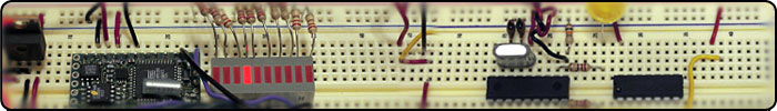
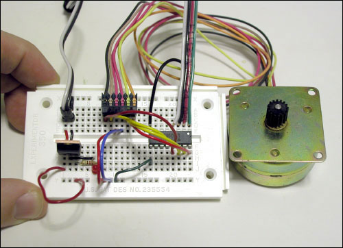 Wiring the Stepper Motor: Based on the truth table I found the coil pattern to be 130 Ohms between the orange to red1, yellow to red1, tan to red2, and black to red2. A total of 260 Ohms resulted between orange to yellow, and tan to black. This is illustrated in the figure below.  ULN2004A: The next step was to connect the proper wires from the stepper motor to the ULN2004A Darlington transistor. The next figure shows how this was done.The outer coils, orange, yellow, tan, and black are connected to the output pins (16-13) of the ULN2004A. Pin 9 of the ULN2004A is connected to the +12VDC supply. Note that wires red1 and red2 are also connected to the +12VDC.  BX-24 Microcontroller: Note the stepper motor requires 12 volts so I decided to put the stepper circuit on a separate breadboard (note that the voltage regulator is used only to supply 5 volts to the LED so I know that power is going to the ULN2004A and stepper motor). The I/O pins from the BX-24 are connected to the ULN2004A as shown in the last figure. I used the BX-24 code below to step the motor in the proper sequence: 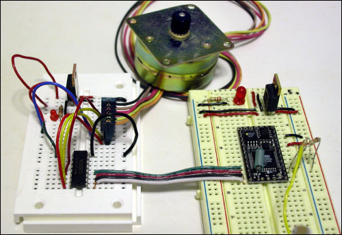
dim motorStep(1 to 4) as byte
dim thisStep as integer

sub main()
  call delay(0.5) ' start program with a half-second delay
  dim i as integer

  ' save values for the 4 possible states of the stepper motor leads
  ' in a 4-byte array. the stepMotor routine will step through
  ' these four states to move the motor. This is a way to set the
  ' value on four pins at once. The eight pins 5 through 12 are
  ' represented in memory as a byte called register.portc. We will set
  ' register.portc to each of the values of the array in order to set
  ' pins 9,10,11, and 12 at once with each step.

  motorStep(0) = bx0000_1010
  motorStep(1) = bx0000_0110
  motorStep(2) = bx0000_0101
  motorStep(3) = bx0000_1001

  ' set the last 4 pins of port C to output:
  register.ddrc = bx0000_1111
  ' set all the pins of port C low:
  register.portc = bx0000_0000

  do
   ' move motor forward 100 steps.
   ' note: by doing a modulo operation on i (i mod 4),
   ' we can let i go as high as we want, and thisStep
   ' will equal 0,1,2,3,0,1,2,3, etc. until the end
   ' of the for-next loop.

   for i = 1 to 100
     thisStep = i mod 4
     call stepMotor(thisStep)
   next

  ' move motor backward
   for i = 100 to 1 step -1
     thisStep = i mod 4
     call stepMotor(thisStep)
   next

  loop

end sub

sub stepMotor(byref whatStep as integer)
  ' sets the value of the eight pins of port c to whatStep
  register.portc = motorStep(whatStep)
  call delay (0.1) ' vary this delay as neede to make your stepper step.
end sub
|
| Copyright © 2006 Jason Babcock. All rights reserved. | Valid CSS Valid XHTML 1.0 |