 |
| home | eyetracking | computing | aesthetics | research |
| software -- microcontrollers/breadboards -- generative algorithms |
|
LinearStrip Panoramic Turntable Version 2 (BX-24) Introduction: For my first panoramic turntable I used a stepper motor and gear assembly from an old fax machine. While that system allowed me to make good panoramic images, the turnable did not rotate 360 degrees smoothly because the camera wobbled slightly on top of the small gear assembly. When making linearstip images with the old turnable I noticed some places in the image where artifacts resulted from the unstable gear system. I decided to rebuild the turntable and design my own gear system to get a smooth 360 degree rotation and improve stability. This entry describes the process of building a new panoramic turntable (from prototype to final design) as shown in Figure 1. 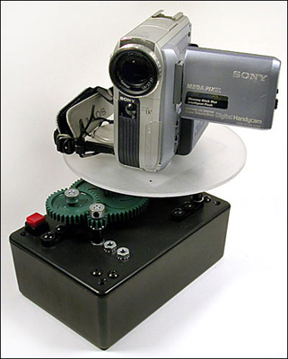 Figure 1 - Final design of the linear-strip panoramic turntable.
Finding the Gears
I've been on the lookout for a good set of gears and I came across the company Vex Robotics (www.vexrobotics.com). The company makes hardware for beginning robot builders, and you can buy kits online or from Radioshack. For some of the first experiments I purchased a few servo motors, some metal hardware/screws, and the Vex Robotics gear kit. Initially I used a servo motor as the driving motor, but I found the servo to be loud and a bit distracting. I decided to go back to using a stepper motor because it is quieter, easy to control, and has reasonable torque. First Prototype Figures 2 - 4 show the first prototype that I built using the Vex Robotics hardware (i.e. screws, metal plates, and gears) and a Howard Industries (P/N 1-19-3801), 12 volt, 1.8 degree stepper motor. The motor is a 5 wire unipolar stepper so I was able to use similar code that I used for the first panoramic turntable. Figure 2 shows the gear assembly. For this design I used a compound gear system consisting of four gears. A large 84 tooth gear is driven by a smaller 12 tooth gear mounted to the stepper motor's shaft. This gives a gear ratio of 84:12, or 7:1. The ratio is doubled by adding a second 84:12 gear combination as shown in Figures 2 and 3. I'll discuss a better gear design in more detail in subsequent sections. As in my previous design, the stepper motor is driven with a ULN2004A and BX-24 (Figure 3). 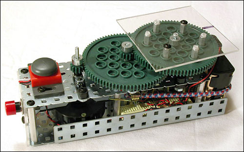 Figure 2 - First prototype of the panoramic turntable. Notice the compound gear assembly.
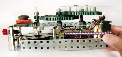 Figure 3 - Side detail of the compound gear assembly and 12 volt power supply.
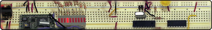
 Figure 4 - Breadboard circuit using a ULN2004A and BX-24 microcontroller.
Again, the stepper's wiring configuration is determined by measuring the resistance of each wire (as compared to all other wires) using a multimeter and building a truth table (not shown here, but nearly identical to the other stepper truthtable examples...go here more details). The stepper motor coil configuration is shown in Figure 5, and pin diagram for the microcontroller and stepper motor chip (ULN2004A) is shown in Figure 6. BX-24 Microcontroller: The stepper motor runs on 12 volts so I used 8 AA batteries and wired the power supply in parallel so that the stepper motor and ULN2004 get 12 volts, and the BX-24 gets 12 volts regulated down to 5 volts. The I/O pins from the BX-24 are connected to the ULN2004A as shown in Figure 6.  Figure 5 - Wire configuration for Howard Industries (P/N 1-19-3801) stepper motor.
 Figure 6 - ULN2004A, BX-24, and unipolar stepper motor pin configuration.
Problems With First Prototype: The first prototype worked really well, but there were a couple of issues I wanted to resolve in the final design. The first major problem was vibration. The stepper motor creates a small amount of vibration and this seemed to be amplified by the metal housing that I used to support the motor and gear assembly. Also, the metal housing and 12 volt power supply made the turntable a little heavy and I was looking for ways to reduce weight and make the turntable smaller. Finally, I wanted to try a gear ratio that would produce a slower rotation speed so I could fine-tune the exact rotation using software/microcontroller. Final Design Figures 7 - 10 show the key elements of the final design. 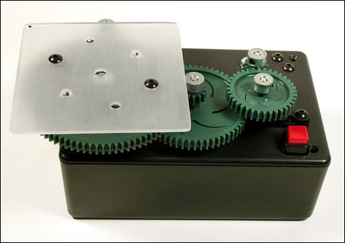 Figure 7 - Final turntable system using a new gear design and project box.
Final Gear Design: Figure 8 shows the final gear assembly. The purpose of this compound gear system is to slow down the rotation of the stepper motor and increase the torque. To describe this particular gear design I've "color coded" the gears so it will be easier to explain what I'm doing. First, if you look on the right side of the image you'll see an arrow pointing to the driving gear. This is the small 12 tooth gear attached to the axle of the stepper motor. Note that this gear connects with the teeth of the blue gear, which has 36 teeth. This creates a gear ratio of 36:12 (or 3:1). Attached to the shaft of the blue gear is another smaller gear with 12 teeth. This gear connects with the teeth of the red gear which has 60 teeth (creating a ratio of 60:12, or 5:1). Attached to the shaft of the red gear is again a smaller 12 tooth gear that connects to the largest 84 tooth gear (creating an 84:12 ratio, or 7:1). Finally, there is a second 12 tooth gear that simply provides stabilization and has no effect on the speed or torque. To calculate the total torque of the system we multiply the ratios of each of the three gear sets. For example 36:12 x 60:12 x 84:12 = 3:1 x 5:1 x 7:1 = 105:1. This means that the torque, or force of the motor, is 105 times the inital torque of the motor without any gears. Notice in this example that we are trying to slow down the motor so the driving gear (for each compound set) is always smaller than the gear being driven. This slows down the speed of the motor. Thus, to calculate the final speed we use the inverse ratio of the torque. Thus, we multiply the initial speed of the motor by 1/105, meaning a huge reduction in speed. 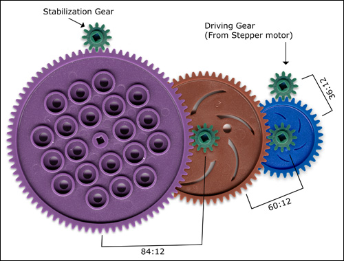 Figure 8 - Color coded compound gear assembly. Each gear set (i.e. blue:green, red:green, and
purple:green ) steps down the motor speed and increases torque. The total speed reduction is 1/105 times the original speed of the motor, and the total torque (i.e. force) is multiplied by 105. Construction and Battery Supply: To house the motor, circuit board, and batteries I used a project box as shown in Figure 9. With some experiment I found that I could power both the circuit board and motor with a single 9V battery, but that did not give me a very long battery life. I decided to mount a second battery to the lid next to the motor. Both 9v batteries are wired in parallel to provide 9Vs at twice the battery life. The circuit board gets 9Vs regulated down to 5Vs, and the + ULN2004A takes the raw 9Vs. I can run the turntable for about 4 to 5 hours continuously! 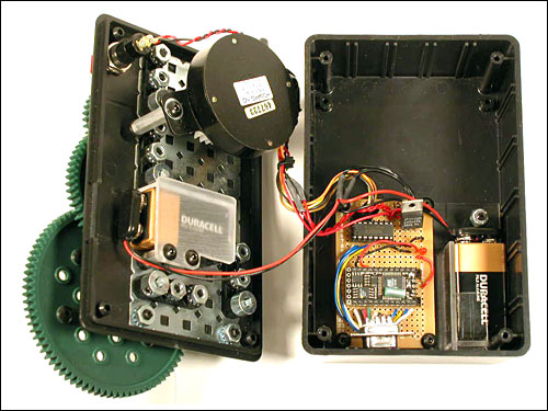 Figure 9 - Housing for the battery supply and circuit board.
Circuitboard Close Up: In previous designs I used just a breadboard for circuit construction. This time I soldered the components to a prototype circuit board. The BX-24 and ULN2004 are mounted using sockets so I can swap them out incase of damage. I also soldered a serial port connector to make it easy to program and make upgrades to the code. I also constructed a plexiglass plate which holds the batteries in place (see Figure 9 for the other battery mount). 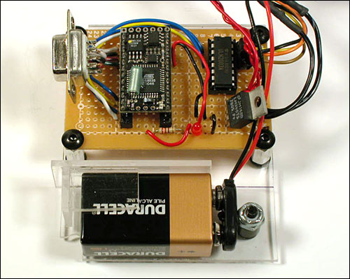 Figure 10 - Closeup of the circuitboard with BX-24 microcontroller, serial port, and battery.
Stepper Code: This code is pretty much identical to the code in my previous examples except that I have simplified it a bit and changed the timing.
dim motorStep(1 to 4) as byte
dim thisStep as integer

sub main()
  call delay(0.5) ' start program with a half-second delay
  dim i as integer

  ' save values for the 4 possible states of the stepper motor leads
  ' in a 4-byte array. the stepMotor routine will step through
  ' these four states to move the motor. This is a way to set the
  ' value on four pins at once. The eight pins 5 through 12 are
  ' represented in memory as a byte called register.portc. We will set
  ' register.portc to each of the values of the array in order to set
  ' pins 9,10,11, and 12 at once with each step.

  motorStep(0) = bx0000_1010
  motorStep(1) = bx0000_0110
  motorStep(2) = bx0000_0101
  motorStep(3) = bx0000_1001

  ' set the last 4 pins of port C to output:
  register.ddrc = bx0000_1111
  ' set all the pins of port C low:
  register.portc = bx0000_0000

  do
   for i = 0 to 4 step 1
     thisStep = i mod 4
     call stepMotor(thisStep)
   next

  loop

end sub

sub stepMotor(byref whatStep as integer)
  ' sets the value of the eight pins of port c to whatStep
  register.portc = motorStep(whatStep)
  call delay (0.1) ' vary this delay as neede to make your stepper step.
end sub
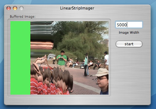 Figure 11 - Screen grab of the LinearStrip Imager software used to pull the image off the DV camcorder.
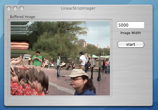 Figure 12 - As the buffer gets filled, the image is "striped" from the DV camera line by line.
Image Capture and Processing: As seen in Figure 1, I use a Sony Mini-DV camcorder (DCR-PC105) to capture footage of the scene as it rotates on the turntable. Basically the camera spins on the table and the panoramic scene is recorded onto the miniDV tape. I wrote some software (Figures 11 and 12) for Mac OS X to do the image processing which converts the video panorama into a single image panorama. Because of the gear design, the speed is very slow (usually about 3 minutes to do a full 360 pan). The pantable rotates slowly because the software strips out one column of pixels every 30th of a second for each video frame. The column of pixels are written out to a raw binary file and eventually converted into a TIFF image. Figures 13 shows slices of the original image. The thumbnail panorama in Figure 14 provides a link to the larger 240x5000 pixel image.      Figure 13 - Sections of the linear-strip panoramic image created from the miniDV video footage.
 Figure 14 - click on
|
| Copyright © 2006 Jason Babcock. All rights reserved. | Valid CSS Valid XHTML 1.0 |