 |
| home | eyetracking | computing | aesthetics | research |
| software -- microcontrollers/breadboards -- generative algorithms |
|
Driving a Bipolar Stepper Motor: This entry shows the configuration I used to make a NMB (Minebea Electronics Co.) PM35L-048, 24VDC, 9.4 Ohm unipolar stepper motor work. I salvaged several of these motors from some Xerox inkjet printers. The motors were labeled well and I found manufacture specifications on-line. I was not able to find a wire diagram so I defaulted to making a truth table as I had done for unipolar steppermotors. Most steppers with 4 wires can usually be identified as bipolar stepper motors, which can be driven with a dual H-bridge IC such as the SN754410 by Texas Instruments. The first thing to figure out is how the stepper's wires are configured by measuring the resistance of each wire (as compared to all other wires) using a multimeter. I made a truth table as shown below (note that all values are in Ohms and inf stands for infinite resistance):
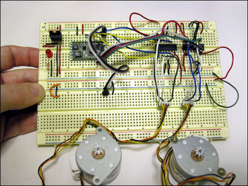 Wiring the Stepper Motor: Based on the truth table I found the coil pattern to be 9.4 Ohms between the brown to black, and orange to yellow. This is illustrated in the figure below. 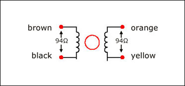 SN754410 Dual H-Bridge: The next step was to connect the proper wires from the stepper motor to the Dual H-Bridge chip. The next figure shows how this was done. Each coil acts as its own motor and is connected to the h-bridge pins (3 and 6, and 14 and 11) of the SN754410. Pin 8 of the SN754410 is connected to the motor's voltage supply (usually +12VDC). It is recommended to build the circuit for the BX-24 and the SN754410 on the same board and put the power supply for the motor on a separate board. If you do this, remember to connect ground from the motor supply board to the board housing the BX and dual H-bridge. 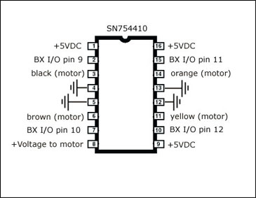 BX-24 Microcontroller: This particular stepper motor requires 24 volts. However, we decided to use a lower voltage supply, which sacrafices the torque. I decided to put the motor supply on a separate breadboard using a Radio Shack 9V AC/DC adaptor. The great thing about stepper motors is that the code on the BX is identical since you are just sending 4 pins high or low in a particular sequence. I used the code below to step the motor in the proper sequence:
dim motorStep(1 to 4) as byte
dim thisStep as integer

sub main()
  call delay(0.5) ' start program with a half-second delay
  dim i as integer

  ' save values for the 4 possible states of the stepper motor leads
  ' in a 4-byte array. the stepMotor routine will step through
  ' these four states to move the motor. This is a way to set the
  ' value on four pins at once. The eight pins 5 through 12 are
  ' represented in memory as a byte called register.portc. We will set
  ' register.portc to each of the values of the array in order to set
  ' pins 9,10,11, and 12 at once with each step.

  motorStep(0) = bx0000_1010
  motorStep(1) = bx0000_0110
  motorStep(2) = bx0000_0101
  motorStep(3) = bx0000_1001

  ' set the last 4 pins of port C to output:
  register.ddrc = bx0000_1111
  ' set all the pins of port C low:
  register.portc = bx0000_0000

  do
   ' move motor forward 100 steps.
   ' note: by doing a modulo operation on i (i mod 4),
   ' we can let i go as high as we want, and thisStep
   ' will equal 0,1,2,3,0,1,2,3, etc. until the end
   ' of the for-next loop.

   for i = 1 to 100
     thisStep = i mod 4
     call stepMotor(thisStep)
   next

  ' move motor backward
   for i = 100 to 1 step -1
     thisStep = i mod 4
     call stepMotor(thisStep)
   next

  loop

end sub

sub stepMotor(byref whatStep as integer)
  ' sets the value of the eight pins of port c to whatStep
  register.portc = motorStep(whatStep)
  call delay (0.1) ' vary this delay as neede to make your stepper step.
end sub
|
| Copyright © 2006 Jason Babcock. All rights reserved. | Valid CSS Valid XHTML 1.0 |